
Honeywell 4000 Installation Manual: A Comprehensive Plan
This manual details the setup of the Honeywell 4000 system, encompassing components like smoke and CO detectors, and wireless sensors.
It covers wiring, programming, and troubleshooting, ensuring a secure and functional installation for optimal safety and peace of mind.
The Honeywell 4000 system represents a significant advancement in home and business security, offering a comprehensive and integrated approach to safety. This system is designed for reliability and ease of use, providing protection against fire, carbon monoxide, and potential intrusions. It’s a versatile solution adaptable to various property sizes and configurations.
Central to the Honeywell 4000’s functionality is its ability to seamlessly integrate a range of sensors, including smoke detectors, carbon monoxide detectors, and wireless sensors. This interconnectedness ensures that any detected threat triggers a coordinated response, maximizing safety. The system’s architecture allows for both wired and wireless components, offering flexibility during installation.
This installation manual provides a step-by-step guide to ensure a successful setup. It covers everything from pre-installation checks and component overview to detailed wiring instructions and system programming. Following these guidelines will enable you to harness the full potential of the Honeywell 4000 system, creating a secure environment for your property and its occupants.
System Components Overview
The Honeywell 4000 system comprises several key components working in harmony to deliver robust security. The central control panel serves as the brain of the system, managing all sensor inputs and outputs. This panel requires a stable power supply and proper wiring for optimal performance.
A crucial element is the range of sensors, including smoke detectors strategically placed to provide early fire detection. Carbon monoxide detectors are equally vital, safeguarding against this silent and deadly threat. Wireless sensors offer flexibility, allowing for easy expansion and placement in areas where wiring is challenging.
Additional components may include key fobs for remote arming/disarming, siren(s) for audible alerts, and potentially, network connectivity modules for remote monitoring and control. Understanding the function of each component is essential for a successful installation and ongoing system maintenance. Proper component placement, as detailed later, is critical for maximizing system effectiveness.
Pre-Installation Checklist
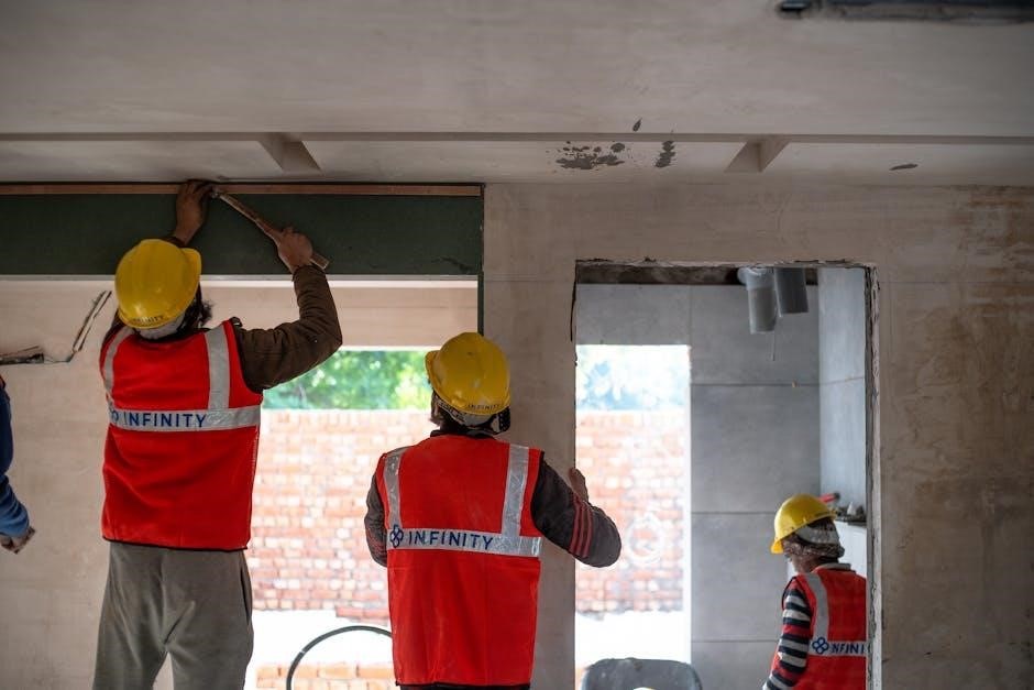
Before commencing the Honeywell 4000 installation, a thorough pre-installation checklist is paramount. This ensures a smooth, efficient, and safe process. First, verify all components are present and undamaged, referencing the packing list. Confirm the control panel location allows for easy access and secure mounting.
Next, assess the wiring routes, identifying potential obstacles and ensuring sufficient cable length. Plan sensor placement based on the guidelines provided in this manual, considering coverage areas and potential interference. Check for existing wiring that may need to be relocated or modified.

Crucially, review all safety precautions (detailed in the following section) and ensure you understand them completely. Gather all necessary tools and materials, preventing delays during installation. Finally, familiarize yourself with the system’s basic programming requirements to streamline the configuration process post-installation. A well-prepared start minimizes complications.
Required Tools and Materials
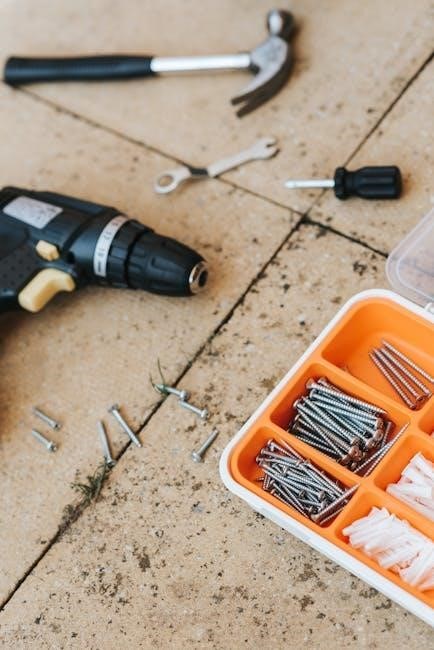
For a successful Honeywell 4000 installation, gather the following tools and materials. Essential tools include a screwdriver set (Phillips and flathead), wire strippers, a wire crimper, a drill with appropriate drill bits for mounting surfaces, and a level to ensure proper panel alignment.
Necessary materials encompass appropriately sized wiring (refer to the wiring diagram), wire connectors (e.g., wire nuts), mounting screws and anchors suitable for the wall type, and cable ties for neat wire management. A multimeter is highly recommended for testing continuity and voltage.

Depending on the system configuration, you may also require a network cable (Ethernet) for connectivity, a Wi-Fi adapter if wireless setup is chosen, and labeling tape for clear wire identification. Don’t forget a pencil for marking drill points and a safety glasses for eye protection during drilling and wiring. Having everything readily available streamlines the process.
Safety Precautions
Prioritizing safety is paramount during Honeywell 4000 installation. Always disconnect power to the circuit at the breaker box before commencing any wiring work. Verify the power is off using a non-contact voltage tester. Wear appropriate personal protective equipment (PPE), including safety glasses and insulated gloves.
Exercise caution when drilling into walls or ceilings, ensuring no hidden pipes or electrical wiring are present. If unsure, consult a qualified professional. Properly ground the control panel to prevent electrical shock. Avoid working in wet or damp conditions.
Handle wiring carefully to prevent damage or short circuits. Follow all local electrical codes and regulations. If you are uncomfortable performing any aspect of the installation, seek assistance from a licensed electrician or security professional. Proper installation minimizes risks and ensures system reliability and longevity.
Control Panel Installation
Begin by selecting a central, accessible location for the control panel, ensuring it’s protected from extreme temperatures and moisture. Mounting the Control Panel requires secure attachment to a solid surface using appropriate screws and anchors, verifying level installation.
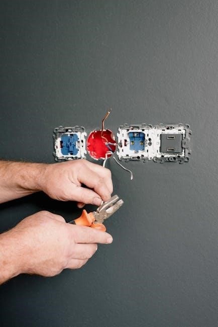
Wiring the Control Panel – Power Supply involves connecting the transformer to a dedicated circuit, adhering to local electrical codes. Double-check polarity before securing connections. Wiring the Control Panel – Sensor Connections necessitates identifying each zone and connecting corresponding sensor wires to the designated terminals.
Carefully label all wiring for future maintenance. Ensure all connections are tight and secure. Before powering on, visually inspect all wiring for errors. A properly installed control panel forms the core of a reliable security system.
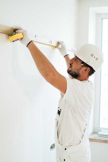
Mounting the Control Panel
Selecting the optimal location is crucial; choose a central, dry, and easily accessible spot, away from potential interference sources. The control panel should be mounted on a structurally sound wall, capable of supporting its weight. Utilize the provided mounting template to accurately mark drill locations, ensuring proper alignment.
Drill pilot holes using a drill bit appropriate for the wall material. Insert wall anchors if necessary, providing a secure base for the mounting screws. Carefully align the control panel with the pre-drilled holes and securely fasten it using the supplied screws.
Verify the panel is level and firmly attached. Avoid over-tightening screws, which could damage the enclosure. A stable and properly mounted control panel is essential for reliable system operation.
Wiring the Control Panel – Power Supply
Before commencing, disconnect the main power supply to the circuit where the control panel will be connected. Identify the designated power input terminals on the control panel – typically labeled for voltage and ground. Using appropriately sized wiring (refer to local electrical codes), connect the hot (live), neutral, and ground wires to the corresponding terminals.
Ensure all connections are secure and that no bare wires are exposed. Double-check the polarity to prevent damage to the control panel. A secure and correctly wired power supply is fundamental for consistent system performance.
Once wiring is complete, carefully inspect all connections. Restore power to the circuit and verify the control panel powers on correctly. If no power is detected, immediately disconnect power and re-examine the wiring for errors.
Wiring the Control Panel – Sensor Connections
Identify the designated sensor input terminals on the control panel, typically labeled for each zone or sensor type (e.g., smoke, CO, door/window). Refer to the system’s wiring diagram for specific terminal assignments. Using low-voltage wiring (typically 18-22 gauge), connect each sensor to its corresponding terminal.
For wired sensors, ensure correct polarity if applicable; Securely fasten the wires to the terminals, avoiding loose connections. Wireless sensors will not require physical wiring to the panel, but their IDs must be programmed into the system later.
Carefully label each wire during installation for easy identification during troubleshooting. Once all sensors are connected, double-check the wiring against the diagram before proceeding to system programming and testing.
Sensor Installation
Proper sensor placement is crucial for optimal system performance. Begin by identifying ideal locations based on the sensor type – smoke detectors benefit from high ceilings and open areas, while carbon monoxide detectors should be near sleeping areas. Follow local building codes regarding sensor placement requirements.
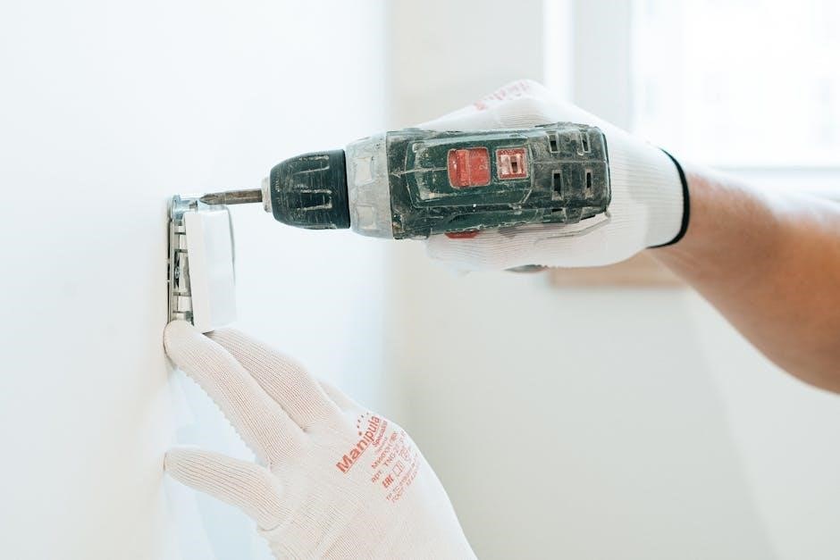
Mount sensors securely using the provided hardware, ensuring they are firmly attached to the surface. For wireless sensors, verify adequate signal strength to the control panel before final mounting. Avoid placing sensors near obstructions like furniture or curtains that could interfere with their operation.
Test each sensor after installation to confirm it is communicating with the control panel. Refer to the individual sensor manuals for specific testing procedures. Regularly scheduled testing is recommended to maintain system reliability.
Smoke Detector Placement Guidelines
Strategic placement of smoke detectors is paramount for early fire detection. Install detectors on ceilings or high on walls, as smoke rises. Avoid corners where airflow might be restricted, hindering smoke from reaching the sensor. Each detector should protect a designated area, adhering to manufacturer specifications and local fire codes.
Interconnected smoke detectors are highly recommended; when one activates, all sound the alarm, providing comprehensive warning throughout the home. Do not install smoke detectors in kitchens or bathrooms where cooking fumes or steam could trigger false alarms. Maintain a safe distance from heating appliances and air vents.
Regularly test smoke detectors (monthly) using the test button. Replace batteries annually, or as indicated by the detector’s low-battery warning. Replace the entire detector every 10 years, as sensitivity diminishes over time.
Carbon Monoxide Detector Placement Guidelines
Carbon monoxide (CO) is a silent, odorless killer, making proper detector placement crucial. Install CO detectors on each level of your home, including the basement. Prioritize locations near sleeping areas, as early detection during sleep is vital.
Do not install CO detectors near fuel-burning appliances (furnaces, water heaters, fireplaces) as brief CO spikes during startup can cause false alarms. Maintain a distance of at least 15 feet. Avoid obstructed areas like behind furniture or curtains, which can impede CO flow to the sensor.
Test CO detectors monthly using the test button. Replace batteries annually, or when the low-battery warning sounds. Replace the entire detector every 5-7 years, as sensor accuracy degrades over time. Ensure detectors comply with local regulations and safety standards for optimal protection against CO poisoning.
Installation of Wireless Sensors
Wireless sensors offer flexibility in placement, avoiding the need for extensive wiring. Begin by verifying strong signal strength at the desired location using the control panel’s signal test mode. Ensure sensors are within the system’s wireless range, typically up to 200 feet, but obstructions can reduce this.
Mount sensors securely using the provided screws or adhesive tape, following the manufacturer’s instructions. Avoid metal surfaces, which can interfere with wireless communication. Register each sensor with the control panel by entering its unique ID number during system programming.
Regularly check battery levels in wireless sensors. Low batteries can cause unreliable operation. Test sensors frequently to confirm proper functionality and communication with the control panel. Consider using a wireless range extender if signal strength is weak in certain areas of your property.
System Programming and Configuration
Initial system setup requires accessing the control panel’s programming mode, typically through a master access code. This allows customization of various system parameters to suit your specific needs. Zone configuration is crucial; assign each sensor to a specific zone (e.g., entry door, living room window) for accurate event reporting.
User code creation enables personalized access. Assign unique codes to family members or authorized users, with varying levels of authority. Manage user codes carefully, changing them periodically for enhanced security. Configure entry and exit delays to prevent false alarms during normal access.
Explore advanced settings such as alarm verification, siren duration, and communication options. Regularly review and update system settings to ensure optimal performance and security. Refer to the detailed programming guide for a comprehensive understanding of all available options.
Initial System Setup
Power on the control panel and allow it to complete its self-test sequence. This ensures all internal components are functioning correctly before proceeding. Access the programming mode using the default master access code (refer to the separate code list document). Immediately change this default code to a unique, memorable one for security.
Set the system clock and date accurately; this is vital for event logging and reporting. Configure the communication settings if utilizing network connectivity (Ethernet or Wi-Fi – see relevant sections). Define the system language and time zone to match your location.
Perform a basic zone test to verify communication with each installed sensor. This confirms proper wiring and sensor functionality. Document all initial settings for future reference and troubleshooting. A successful initial setup is foundational for reliable system operation;
Zone Configuration
Define each sensor’s location within the system by assigning it to a specific zone. Zones represent physical areas like “Front Door,” “Living Room,” or “Basement.” Select the appropriate zone type – instant, delay, or no entry – based on the area’s function and desired response time. Instant zones trigger an alarm immediately, delay zones allow entry time, and no entry zones report tampering only.
Configure zone options such as alarm verification (requiring a second sensor activation) and cross-zoning (requiring multiple zones to trigger an alarm). Enable or disable zone bypass functionality, allowing temporary deactivation of specific sensors. Test each zone individually to confirm correct operation and alarm reporting.
Document the zone configuration for easy reference and future modifications. Proper zone configuration is crucial for accurate alarm identification and efficient response.
User Code Creation and Management
Establish unique user codes for each individual with access to the Honeywell 4000 system. Assign appropriate access levels – Master, Arm/Disarm, or Guest – dictating system control permissions. Master codes possess full system control, Arm/Disarm codes enable arming and disarming, and Guest codes offer limited access.
Choose strong, memorable codes avoiding easily guessable numbers like birthdays or addresses. Enable code change restrictions preventing users from modifying their own codes. Set code expiration dates for temporary access, enhancing security. Monitor user activity logs to track system access and identify potential misuse.
Regularly review and update user codes, especially after personnel changes. Document all user codes and access levels for efficient management and accountability. Proper user code management is vital for maintaining system security and preventing unauthorized access.
Network Connectivity (If Applicable)
If your Honeywell 4000 system supports network connectivity, establishing a stable connection enables remote access and advanced features. Two primary methods are available: Ethernet and Wi-Fi. For Ethernet connection, connect the control panel to your router using an Ethernet cable. Ensure the router has an active internet connection and DHCP enabled for automatic IP address assignment.
For Wi-Fi configuration, access the system programming menu and select the Wi-Fi setup option. Scan for available networks and enter the correct password when prompted. Verify the connection by testing remote access through the Honeywell mobile app or web portal. Ensure strong Wi-Fi signal strength for reliable communication.

Consider network security by enabling WPA2 encryption and regularly updating router firmware. Document network settings for future reference and troubleshooting; Proper network connectivity enhances system functionality and provides convenient remote control.
Ethernet Connection Setup
Establishing an Ethernet connection for your Honeywell 4000 system provides a reliable, wired network link. Locate the Ethernet port on the control panel – typically found on the rear panel. Use a standard Cat5e or Cat6 Ethernet cable to connect the control panel directly to an available port on your router or network switch.
Ensure your router has DHCP enabled; this automatically assigns an IP address to the control panel. If a static IP address is required, consult your network administrator and enter the appropriate settings through the system’s programming menu. Verify the physical connection by checking the link lights on both the control panel and the router.

After connecting, allow the system a few minutes to establish a network connection. Test connectivity by attempting to access the system remotely via the Honeywell mobile app or web interface. Document the assigned IP address for future troubleshooting or network configuration changes.
Wi-Fi Configuration
Connecting your Honeywell 4000 system to Wi-Fi enables remote access and control. Access the system’s programming menu via the control panel interface. Navigate to the network settings and select the Wi-Fi configuration option. The system will scan for available wireless networks within range.
Choose your desired network from the list and enter the correct Wi-Fi password. Ensure the password is case-sensitive. Verify the signal strength; a strong signal is crucial for reliable connectivity. If prompted, select the appropriate security protocol (WPA2 is recommended).
Once configured, the system will attempt to connect to the Wi-Fi network. Confirm successful connection by checking the network status within the programming menu. Test remote access using the Honeywell mobile app or web portal. Document the Wi-Fi network name (SSID) and password for future reference.
Troubleshooting Common Installation Issues
During Honeywell 4000 installation, several issues may arise. If the control panel doesn’t power on, verify the power supply connection and breaker status. For unresponsive sensors, check battery levels and ensure proper enrollment within the system. Communication errors often stem from signal interference; relocate the control panel or sensor if necessary.
False alarms can be triggered by environmental factors like dust or steam. Adjust sensor sensitivity or relocate sensors away from potential sources. Wiring issues can cause intermittent problems; double-check all connections for tightness and correct polarity. If the system fails to connect to Wi-Fi, verify network credentials and signal strength.
Consult the system’s error logs for specific diagnostic codes. Refer to the full installation manual for detailed troubleshooting steps. Contact Honeywell support if issues persist beyond basic troubleshooting.
System Testing and Verification
Post-installation, thorough testing is crucial for the Honeywell 4000 system’s reliability. Begin with a zone test, activating each sensor individually to confirm proper communication with the control panel. Verify alarm transmission to the monitoring center (if applicable) by triggering a sensor and confirming receipt of the signal.
Test the system’s response to power outages by simulating a power loss and ensuring the backup battery activates. Walk-test all wireless sensors to confirm signal strength throughout the protected area; Check the functionality of all programmed user codes, verifying access and control permissions.
Review event logs for any errors or anomalies. Document all test results for future reference. Ensure all users are familiar with system operation and emergency procedures. A fully tested system provides peace of mind and reliable protection.
Honeywell Experion PKS System Structure and Function
The Honeywell Experion PKS utilizes a distributed server architecture (DSA), enabling integration of multiple process control systems and control units across geographically dispersed locations. This structure enhances scalability and redundancy, crucial for complex industrial operations.
Experion PKS features a robust communication network facilitating real-time data exchange between servers, controllers, and operator stations. Its core functions include process control, advanced process control, historical data archiving, and alarm management. The system supports various communication protocols ensuring interoperability with existing plant infrastructure.
Experion PKS provides a unified operator interface for monitoring and controlling the entire process. Advanced analytics and reporting tools enable optimization and improved decision-making. Security features protect against unauthorized access and cyber threats, safeguarding critical operations.